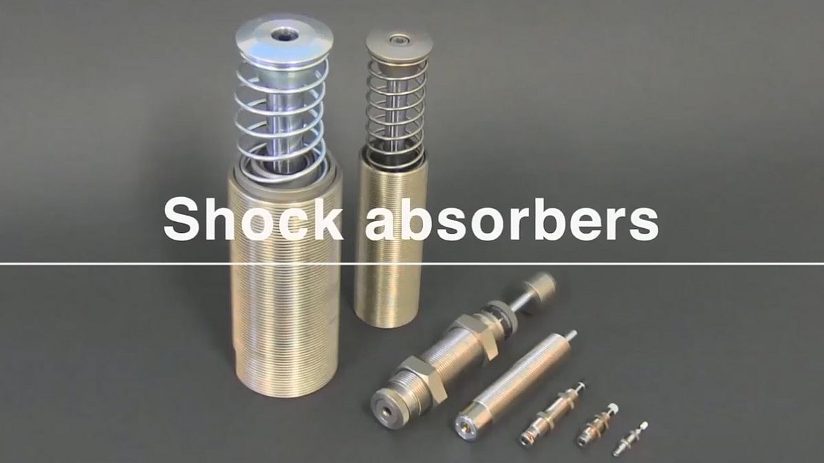
Industrial Shock Sbsorbers
Extremly efficient impact absorbtion
Industrial shock absorbers are widely used machine elements to smoothly decelerate moving loads. They convert damaging kinetic energy into harmless thermal energy and thereby increase process speed, production quality, durability of production facilities and reducing operation noise.
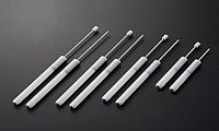
The product portfolio includes sizes from M4 to M80 and absorbing energy from 0.1 to 6’000 J.
The design variations include adjustable, non-adjustable, single orifice, multi orifice, rolling diaphragm seal, front-back adjustment deal, double direction specification, emergency stops, stopper bolts.
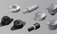
Applications


Principle of energy absorbtion
To increase the productivity of industrial machines, such as assembling machines, conveying systems or machines tools, their operating parts work faster. The resulting impact, vibration and noise cause adverse effects on the machine's performance, on the life time and on the working environment. An industrial shock absorber is an extremely convenient hydraulic buffer that can eliminate these effects. There are similar devices made of rubber, springs or devices that use pneumatic pressure, but none of them rival the absorption characteristics of the hydraulic type, as illustrated below.
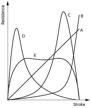
Rubber (A)
The rubbers elastic deformation captures the impact energy and this energy is then accumulated in the rubber. As a result, the accumulated energy works as a repulsive force and a rebound being generated. Therefore, it is not an efficient impact absorber. On the other hand, is is extremely affordable and its installation is easy.
Spring (A)
Like the rubber type, it captures the impact through elastic deformation and stores it as elastic energy. Once the impelling force is diminished, the stored energy repels, causing a rebound.
Pneumatic pressure (B)
It uses pneumatic pressure to absorb impact, but because the compressed air is released to the atmosphere through an orifice, the energy does not accumulate. However, unless the rapid compression and releasing action through the orifice is well balanced, a rebound occurs.
Hydraulic pressure (C, D, E)
It uses oils velocity-squared resistance as well a viscosity resistance to absorb energy, which is then converted into heat and released into the atmosphere. As a result, extremely efficient impact absorption is possible. A relative compact design is capable of absorbing large impacts and depending on its structure, the impact absorption characteristics can be modified.
- (C) Orifices sizes are too big. The shock absorber is too soft and no decelaration until several orifices are closed. High pressure at end of stroke, high reaction force as the energy is mainly dissipated in few milimiters.
- (D) Orifices size are too small, shock absorber is too hard or single orifice (dashpot). Peak of pressure at the beginning of stroke, high reaction force as the energy is mainly dissipated in few milimiters.
- (E) Linear deceleration. Internal pressure is constant over the stroke, reaction force is linear and minimized. This is the best curve and shock absorber selection.
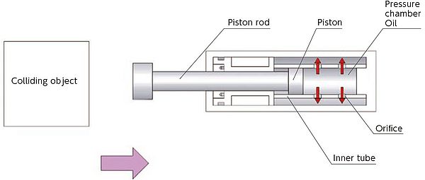
Function of hydraulic shock absorber
When a moving object hits the piston rod, the motion is transferred to the oil in the pressure chamber through the piston rod. As a result, the oil inside the pressure chamber flows out of the orifices, which converts the discharged energy into heat. The metering orifices are arranged at the stroke in a way to slow down the mass with a constant damping force. The hydraulic pressure is kept almost constant during the entire deceleration process in order to provide a linear deceleration. As the energy is thus totally dissipated as heat, there is no rebound.